Notes on my DIY modular synth journey
Feb 21, 2022I want to build a DIY modular synthesizer. A lot of the music I enjoy listening comes from synthesizers, so I want to experiment with it. Moreover, I haven't done any analog electronics work in a long time, so I see it as a creative way to get back into analog hardware.
I have no experience with modular synths, so I'll be documenting my work and research here, with links and resources I found useful.
Form factor
There are three things to take into account when building a modular synth. Sizing, power delivery and connectivity.
From what I understand, there are two major form factors used currently, Moog and Eurorack. Moog modules are 5U (U stands for Rack Unit) in height, while Eurorack is 3U. Moreover, Moog uses +12V and -6V voltages for powering modules, while Eurorack is based around +12V/-12V (and +5V for digital modules). Finally, Moog uses 1/4" audio jacks vs the 3.5mm audio jack used by Eurorack.
However, in the past few years, Sam from 'Look Mum No Computer' has come up with a new format called KOSMO that focuses on making it easy to DIY modules. As such:
- It uses +12V/-12V rails be compatible with all the Eurorack power supply units already in circulation
- Sets the front panel height to 200mm, so it's easy to fabricate and source aluminium panels
- Uses 1/4" jacks to help with live performances
For now, I've 3D printed a Eurorack compatible case, but I can see the allure of the KOSMO format and might switch in the future.
Power Supply Unit
There are various ready made PSUs for modular synths and even more DIY kits complete with PCB and parts for you to solder. In order to get both +12V and -12V DC outputs, which in practice means 24V difference between the positive and negative rail, there are two common approaches to DIY PSUs. One is to get a 12V AC wall wart (so more than 24V peak to peak) and then build the two 12V and -12V DC rails using a 7812 and 7912 voltage regulators. The other much simpler option is to get two 12V DC PSUs and connect the negative output of one to the positive output of the other. My understanding is that this has some problems because:
- The power supplies need to be isolated, otherwise they might short when connected this way
- Most power supplies are switch-mode PSUs that can introduce noise in the circuit
- You have to wrangle two different PSUs instead of a single one
I went the complete DIY way and made a PSU as described in the first approach from scratch, using a commonly found design (AI Synthesis schematic link, Moritz Klein video of the same design –make sure to add resistors to bleed capacitors if you follow this video). I made some stupid mistakes while making this, like running out of space on the perfboard by not planning things ahead. I had to add some bodge wires as a result, but it works and I made it, so 🤷.
I also made a small power bus board to be able to connect up to three modules, but this is easily upgradeable in the future by daisy chaining more bus boards together. If I go the KOSMO route, I just need to make a different bus board to convert the 16-pin IDC connector to the 4-pin connector. Less pins, less cables, less mess, less cost. I already like the KOSMO approach!
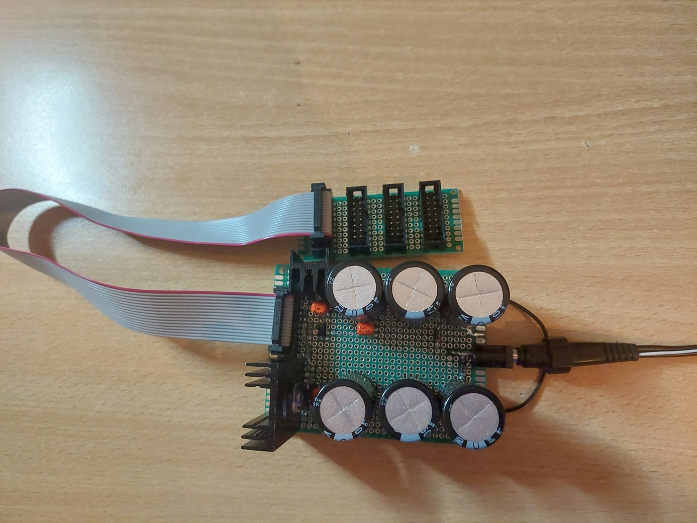
DIY PSU with a bus board
Next steps
That's as far as I've gotten with this project so far. It took a lot of reading and video tutorials to figure out what to build and what the next steps might be. I'll most likely go for a 40106 Schmitt trigger based VCO, but I haven't settled on the design yet. I'll need to experiment with it in a breadboard first.
Resources
- Moritz Klein's YouTube account is a gold mine of information. Their videos go into extreme details on not just how to build a module, but also the working principles behind it.
- Kristian Blåsol's Modular in a Week playlist also showcases DIY modules and how to setup your own modular synth.
- Look Mum No Computer introducing and showcasing KOSMO modules.
- Synth DIY Wiki, a wiki with lots of information and links on DIY synths.
Source: GitHub